GATEKEEPERS, INC.
Wholesale suppliers of Access Control
Systems And Gate Operators
![]()
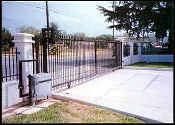
APOLLO 7000 SLIDE GATE OPERATOR
INSTALLATION MANUAL AND OWNER'S GUIDE
IMPORTANT, READ ALL INSTRUCTIONS BEFORE ATTEMPTING INSTALLATION!
SAFETY PRECAUTIONS
(1) When servicing the operator or gate, always disconnect the battery.
(2) Ensure that the gate caution sign is installed on the gate in a position where it can be easily seen.
(3) All rollers and gears should be covered as a safety precaution.
(4) A reversing edge switch is recommended on any slide gate where the possibility of pedestrian traffic exists or if an obstruction is encountered in the closing path of the gate.
(5) If the opening direction presents a potential for hazard, an additional edge switch can be added to stop the gate.
(6) Test all warning and reversing functions of your gate operator system at least once a month to insure safe operation.
|
******************* WARNING******************** 1. NEVER OPERATE THE GATE UNTIL YOU HAVE IT IN FULL VIEW. 2. KEEP CHILDREN AND PETS AWAY FROM THE GATE WHEN IT IS OPENING OR CLOSING. 3. KEEP HANDS, FINGERS, AND FEET AWAY FROM ALL MOVING PARTS. |
| MODEL 7000 SPECIFICATIONS Maximum gate weight400 lbs. Maximum opening20fl. Avg. cycles per day (5 watt solar panel) 12 |
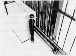
Fig. 1-2 CONTROL BOX INSTALLATION
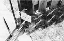
2.) MOUNTING GATE BRACKETS
3.) CHAIN INSTALLATION
Fig. 3-1 CHAIN BOLT INSTALLATION
D) Position gate so it is about halfway closed/open. Thread chain around drive and idler sprockets and pull towards front gate bracket (fig. 3-2).

Fig. 3-2 CHAIN INSTALLATION
E) Adjust chain to proper length then attach remaining chain-bolt to end of chain and bolt to front gate bracket.
F) Check alignment of chain idler sprockets in both vertical and horizontal direction.
G) Adjust nuts on eye bolts to remove excess chain slack (about 1" of slack for every 10 feet of chain). Do not overtighten chain.
H) Attach hood.
4.) LIMIT ADJUSTMENT
A) BE SURE THE HOOD COVERING THE DRIVE AND IDLER SPROCKETS IS SECURED. KEEP PERSONNEL AWAY FROM THE GATE WHILE TESTING.
B) Connect battery (red-positive, black negative).
C) Push test button to activate gate. If gate starts opening, push button twice to stop and reverse gate. Once gate starts closing, push the test button to stop the gate within 3" of the desired close position. Disconnect battery.
D) Mount one of the magnets on the short side of the chain just before the chain enters the hood.
E) Mount the other magnet at a distance of the length of the gate opening less 15" from the first magnet.
F) Reconnect battery and test limits. Re-adjust if necessary. We recommend that the battery be disconnected when changing limits.
G) Once all adjustments have been completed, tack weld all u-bolts to prevent slipping.
5.) SETTING AUTOMATIC CLOSE
Switch #1 on the set of red and white switches activates the automatic close when placed in the "on" position. Apollo slide gate operators are set at the factory for a left-handed closure (if you are standing from inside the property facing out, the gate closes to the left).
If your gate closes to the right, you will have to change the following connections on the terminal strip:
1) Swap the white and orange wires (3 & 5)
2) Swap the red and black wires (1 & 2)
6.) SOLAR PANEL INSTALLATION
1) Determine a suitable mounting location for the solar panel. The solar panel is shipped with 10 feet of cable. Additional cable is available if required. The panel should aim south in the northern hemisphere and north in the southern hemisphere. There should be no obstructions (trees, buildings etc.) that would limit the amount of sunlight that hits the surface of the solar panel.
2) Weld or bolt the solar panel bracket at the selected location to an existing structure.
3) Mount the solar panel to the bracket using the two ¼" bolts and nuts that are shipped on the panel
4) Feed the cable through the hole with a grommet on the side of the control box and connect to battery (red-positive, black-negative). You may need to cut the connection off and re-splice once inside the control box.
6.1
The PC Board is factory pre-programmed as follows:
| Switch #1 | on | Automatic timer to close is activated. |
| Switch #2 | off | 2 second delay until current sensor is activated. |
| Switch #3 | on | Timer to close will activate only from open limit. |
| Switch #4 | off | Allows master side of gate to operate. |
| Switch #5 | off | Allows slave side of gate to operate. (Dual gates.) |
| Switch #6 | off | Maximum run timer will stop gate if time runs out. |
| Switch #7 | on | Maximum run timer value preset about 30 seconds. |
| Switch #8 | on | Timer to close value preset about 20 seconds. |
| Switch #9 | off | For slice gases only.You may adjust the program per attached control board instructions. |
6.2
The pot screw to adjust the current sense sensitivity (Automatic Reverse) is set at minimum sensitivity. See the drawing of circuit board to locate pot screw, if necessary.
The pot screw to adjust the automatic close is set at about 20 seconds. It may be adjusted up to 70 seconds or turned off completely. See drawing of circuit board to locate Timer to Close Adjustment.
PROGRAM SWITCHES
The program switches are the 9 switches located at the top right of the circuit board.
Note: The standard factory settings are in bold lettering.
#1
Turns timer to close on/off
on - timer to close enabled
off - timer to close disabled
#2
Current Sensitivity Option - delay from start until current. sense enabled
on - 4 second delay
off- 2 second delay
#3
Timer to Close Option
on - timer to close works only when open limit switch is activated
off- timer to close works from any point the gate is stopped during opening
#4
Dual Control Option - Slave enable / disable
on - disables slave side of dual control board
off- enables slave side of dual control board
#5
Dual Control Option Master enable / disable
on - disables master side of dual control board
off- enables master side of dual control board
#6
Maximum Run Timer Option
on - stops & reverses gate if timer times out before reaching closed position
off - stops gate if timer times out before reaching closed position
#7
Maximum Run Timer Value
on - 10 to 30 seconds (adjustable)
off- 5 to 15 seconds (adjustable)
#8
Timer To Close Value
on - 20 to 70 seconds (adjustable)
off- 10 to 35 seconds (adjustable)
#9
Open. Stop. Close Switch enable / disable
on - allows for open, stop, close button to operate gate operator
off- disables open, stop, close button
Note: The timer ranges may vary from board to board.
CONTROL BOARD CONNECTIONS
8 Pin Connector (s)
#1 Open Limit Input
#2 Close Limit Input#3 Motor - Positive during open mode, Negative during close mode#4 Motor - Negative during open mode, Positive during open mode#5 Ground#6 Ground#7 Ground - battery negative#8 Battery +12 VDC
7 Pin Connectors
#1 Edge 1 input
#2 Edge 2 input
#3 Ground
#4 Ground
#5 Stop input - used only with 3 button control (N/C)
#6 Close input - used only with 3 button control (N/O)
#7 Open input - used only with 3 button control (N/O)
#8 Ground
#9 Ground
#10 Free Exit input (also recommended telephone gate control)
#11 Ground
#12 Under Gate Loop input
#13 Ground
#14 Safety Loop input
There are an additional 3 connectors for GROUND, INPUT, & 12V. Each of these is fused for 2 amps max.
The EMERGENCY BYPASS CONNECTOR is for use in situations when the control board is not operating correctly.
Unplug the 8 pin white connector from the Master or Slave input and plug into the Emergency Bypass Connector. When
the gate is open enough to get in or out, remove the plug. If the plug is not removed, the motor will stall and
blow fuse F1.
The model 7000 incorporates a mechanical release that is the preferred method of operating the gate manually.
CONTROL BOARD LAYOUT
|
negative & common---------GND normally open----------------INP +12 volts DC -----------------12V |
|
SYMPTOM: Gate opens OK but after closing, opens back up.
1. Automatic reverse sensitivity is set too sensitive. Readjust - CAUTION: Automatic reverse sensitivity should
be set sensitive enough to avoid injury.
2. Too much closing pressure on gate. Readjust magnets on chain.
3. Check that battery voltage is over 12.5 VDC when closing gate.
4. Replace gate control board.
SYMPTOM: Gate doesn't move at all.
1. Check battery connections and polarity. Battery voltage should read above 12.5 VDC.
2. Be sure wiring harness is securely seated in the gate control board.
3. Replace gate control board.
4. Plug the wiring harness into the EMERGENCY BY-PASS connector on the control board. Unplug connector before gate
goes open too far to avoid blowing the fuse.
SYMPTOM: Gate moves only a few feet, then stops.
1. Check battery voltage (should read 12.5 VDC of higher).
2. Check for gate binding or obstruction.
3. Check for damage to gate or rollers. Disconnect chain and manually roll gate to verify free movement.
4. Replace gate control board.
5. Unplug push button from control board (possible bad push button).
SYMPTOM: Gate will open using push button control board but not with transmitter.
1. Check that the code switches inside the transmitter match the code switches in the receiver.
2. Make sure the LED on the transmitter lights when activated. If not, check the battery.
3. Hold the transmitter within 3 inches of the receiver and try to activate. If gate activates, proceed to the
next section.
SYMPTOM: Transmitter works, but not very far away.
Note: Transmission distances will vary according to terrain, obstructions, and lectrica/ interference. Window
tinting on automotive windshields will also cut "own on the range. The normal range inside of a vehicle is
50-100 feet while 100-200 feet may be obtained outside the vehicle.
1. Inspect the antenna. Be sure that the center conductor is penetrating the female connector on the control box.
2. If there is very much metallic material between the antenna and the attempted transmission area, raise the height
of the antenna using a #244 antenna extension kit.
SYMPTOM: Gate randomly opens, closes, and stops for no reason.
1. Check all transmitters, wireless keypads, etc. for a stuck push button.
2. Check the code switch on the transmitter and receiver to be sure all the switches are not in the same position.
3. Disconnect all other devices to see if the problem goes away.
4. Unplug push button from control board (possible bad push button).
QUICK RELEASE
for manual operation
WARNING DISCONNECT BATTERY BEFORE RELEASING GATE
TO RELEASE GATE Pull quick release out and turn ¼ in either direction. Gate can now be manually opened or closed.
TO REENGAGE Turn quick release until it locks into place. Reconnect battery.
GATEKEEPERS, INC.
Sales Toll Free: (800) 378-GATE (4283)
Office: (423) 332-5808
Fax: (423) 332-5840
E-mail:![]() GATEKEEPERS,
INC.
GATEKEEPERS,
INC.
![]()
For questions regarding the functions of this site, please contact Webmaster.