GATEKEEPERS, INC.
Wholesale suppliers
of Access Control Systems And Gate Operators
![]()
|
Apollo 1500/1600 Swing Gate Operator |
|
TABLE OF CONTENTS |
|
INSTALLATION
|
Site Preparation The gate must swing level and not have any significant binding when opening or closing. When the gate is in the closed position, it is recommended that a positive stop exist to prevent the gate from closing beyond the desired close position. A stop tab welded at the top and bottom of the stop post is ideal for a positive stop.  Step
1 - Installation of Pivot Arm Step
1 - Installation of Pivot ArmNote: All Apollo Gate Operators are universal in design and can adapt to gates that are hinged right or left handed. If a 400 Upgrade Kit is to be installed, see 400 Upgrade Kit Addendum for pivot location. 1.1 Locate the 2" x 2" x 19" pivot arm. A carpenter's square or tape measure and level is required for installation. 1.2 Determine the vertical height that the actuator will be attached to the gate. Although a horizontal center bar is normally the ideal location for attachment, the top or bottom of the gate may be preferred. The actuator may be mounted upside down if required. Using a level, align a straight edge with the center of the vertical mounting height and mark this height on the hinge post. The top surface of the pivot arm should be aligned with the lower mark when welding. Note: Standard installation is Pull to Open. See Push to Open instructions otherwise.  With the gate in a closed position, determine the pivot point using a carpenter's square
or tape measure. The pivot point is 13" perpendicular to the gate out from the center of the hinge and 6"
parallel to the gate in the opposite direction of the gate. With the gate in a closed position, determine the pivot point using a carpenter's square
or tape measure. The pivot point is 13" perpendicular to the gate out from the center of the hinge and 6"
parallel to the gate in the opposite direction of the gate. |
||||||||||||||||||||||||||||||
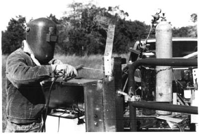
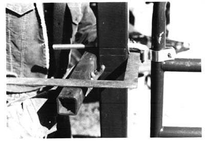 1.3 Cut and weld pivot arm so the ½" hole is aligned with the pivot point. If
the hinge post is round, the end of the pivot arm to be welded should be saddled to assure a good weld. A gusset
is recommended to increase the rigidity of the pivot arm. 1.3 Cut and weld pivot arm so the ½" hole is aligned with the pivot point. If
the hinge post is round, the end of the pivot arm to be welded should be saddled to assure a good weld. A gusset
is recommended to increase the rigidity of the pivot arm.Step 2 - Actuator Installation Align the ½" hole on the rear clevis of the actuator with the ½" hold on the top side of the pivot arm. Connect the actuator to the pivot arm using a ½" x 4" bolt, ½" washer (washer should be on top of the actuator mounting bracket) and ½" lock nut. The joint should be tight enough to give movement significant stiffness.  Connect the front clevis (extension tube
end) of the actuator to the gate attach bracket using a ½" x 3" bolt and ½" lock nut. Connect the front clevis (extension tube
end) of the actuator to the gate attach bracket using a ½" x 3" bolt and ½" lock nut. Step 3 - Control Box and Solar Panel Installation Step 3 - Control Box and Solar Panel Installation3.1 Locate the control box and determine the mounting location. Mount the box close enough to the actuator to allow connection of the 8' actuator cable. Mounting holes are not provided since mounting surfaces will vary from gate to gate. Avoid getting drill shavings on the electronic circuit board. Run the actuator cable through the bottom of the control box and connect the white connector into the white connector on the circuit board labeled MASTER. Do not plug into the EMERGENCY BYPASS connector. It is important that the connector locks into place to assure proper connection.  3.2 Locate the solar panel and its mounting bracket. Attach the solar panel to the mounting
bracket using the two 1¼" nuts located on the bolts in the solar panel frame. The panel should be mounted
within 10' of the control box, due south at a 45º angle and not be obscured for maximum performance. Run the
cable through the bottom of the control box. 3.2 Locate the solar panel and its mounting bracket. Attach the solar panel to the mounting
bracket using the two 1¼" nuts located on the bolts in the solar panel frame. The panel should be mounted
within 10' of the control box, due south at a 45º angle and not be obscured for maximum performance. Run the
cable through the bottom of the control box.Note: You may add up to 150' of 207 Extension Cable to find a suitable location for the solar panel. |
||||||||||||||||||||||||||||||
|
|
5.2 Automatic Reverse Sensitivity The Automatic Reverse Sensitivity adjustment is set at midpoint. Warning: The Automatic Reverse Sensitivity adjustment should be set sensitive enough to prevent serious injury during the operation of the gate. See Control Board Layout for location of the adjustment. Timer to Close The timer to close may be adjusted from 10 to 70 seconds. Control switch 8 doubles the close time when in the ON position. See Control Board Layout for location of the adjustment. . |
|
|
|
|
There are an additional three connectors for ground, input and 12V, all fused for two amps max. The emergency bypass connector is for use in situations when the control board is completely dead.  . |
|
|
A different pivot point and some wiring changes will be necessary for push to open installations. Note that the pivot arm and actuator will protrude into the driveway about 10" when the gate is in the open position. With the gate in the closed position, determine the pivot point using a carpenter's square or tape measure. The pivot point is 6" out from the gate hinge (perpendicular to the gate in the closed position) and 11" parallel to the gate. Remove 6" of cable sleeve from the connector end of the actuator cable. Cut and reconnect the white/orange and red/black wires as shown.  PUSH TO OPEN: TOP, LOCATION OF PIVOT POINT FOR PUSH TO OPEN INSTALLATION; BOTTOM, RE-WIRING DIAGRAM FOR PUSH TO OPEN INSTALLATION . |
|
1600 DUAL GATE OPERATOR ADDENDUM
|
Apollo Dual Gate Operators basically install the same as the Apollo Single Gate Operator with the exception of the following. 1. An additional five watt solar panel and mounting bracket is provided to increase the charging capacity to ten watts. 2. A 38 foot actuator cable is installed on the slave actuator to be mounted on the opposite side of the control box. Installation 1. Install the master actuator following the instructions above. 2. Mount the slave actuator and hardware. 3. Cut the slave actuator cable about one foot from the white connector. Run the remaining cable across the drive through PVC conduit and up through the control box. Cut off any excess cable and reconnect the short piece with the connector using the supplied wire nuts and plug into the slave connector on the control board. Solar Panel Installation The solar panels may be mounted next to each other or may be mounted separately as each panel has its own mounting bracket, cable and battery ring terminal connectors. Both panels should face due south in the northern hemisphere and be unobstructed from shadows, trees and structures. Final Adjustment As you open and close the gates, you will notice that the slave side moves about 2-3 seconds slower than the master. By welding stop tabs on the top and bottom of the master side, the two gates may now be adjusted so the slave gate will close against the stop tabs of the master gate and create enough tension to prevent the gates from moving back and forth. . |
|
|
WARNING: Disconnect battery power before proceeding. Step 1 Establish pivot point as follows:  Locate the short arm and position so that the two ears are pointed into the gate. Mount the end closest to the ears on the pivot arm using a ½" x 4 ½" bolt and ½" lock nut. Do not use any washers. The joint should be tight enough to give movement significant stiffness. Step 2 Locate the long arm and position so the two perpendicular ears are pointed into the gate and the end with the extended ears align with the end of the short arm. Connect the long arm to the short arm using a ½" x 3" bolt and ½" lock nut. Again, the joint should be tight enough to give movement significant stiffness. Step 3 Mount the actuator between the two sets of ears using ½" x 3" bolts. Continue with step three on the normal installation. . |
|
|
SYMPTOM: Gate opens fine but after closing, opens back up. 1. Automatic reverse sensitivity is set too sensitive. Readjust. CAUTION: Automatic reverse sensitivity should be set sensitive enough to avoid injury. 2. Too much closing pressure on gate. Readjust actuator. 3. Gate is in a bind when closing. Readjust gate. 4. Check that battery voltage is over 12.5 VDC when closing gate. 5. Replace gate control board. . |
|||
SYMPTOM: Gate doesn't move at all. 1. Check battery voltage (should read 12.5 VDC or higher). 2. Be sure actuator connector is securely seated in the gate control board. 3. Check for damaged actuator cable. 4. Replace gate control board. 5. Plug the actuator cable into the EMERGENCY BYPASS connector on the control board. Unplug connector before gate goes open too far to avoid blowing the fuse. . |
|||
SYMPTOM: Gate moves only a few feet, then stops. 1. Check battery voltage (should read 12.5 VDC or higher). 2. Check for gate binding or obstruction. 3. Check for bent actuator screw. 4. Replace gate control board. . |
|||
SYMPTOM: Gate surges too much when moving. 1. Check for movement in pivot arm when gate is moving. Pivot arm should be rigid for proper operation. 2. Check for loose bolts. 3. Gate is too limber. Stiffen gate with angle iron or square tubing. . |
|||
SYMPTOM: Gate randomly opens, closes and stops for no reason. 1. Check all transmitters and wireless keypads for a stuck push button. 2. Disconnect all other devices to see if the problem goes away. 3. Disconnect push button from control board (possible bad push button). . |
GATEKEEPERS, INC.
Sales Toll Free: (800) 378-GATE (4283)
Office: (423) 332-5808
Fax: (423) 332-5840
E-mail:![]() GATEKEEPERS,
INC.
GATEKEEPERS,
INC.
 Step
4 - Test & Adjustments
Step
4 - Test & Adjustments 4.3 Reconnect the actuator to the circuit board. Press the black button on the side of the
control box and observe operation. The gate will open about 100 degrees, pause for about 20 seconds, then close.
If no major adjustments are necessary, disconnect the actuator from the circuit board and permanently secure the
gate bracket to the gate using the provided hardware or by welding. Connect the actuator extension to the gate
bracket using a ½" x 3" bolt and ½" lock nut. Reconnect the actuator to the circuit
board. The gate operator is now ready for final adjustment.
4.3 Reconnect the actuator to the circuit board. Press the black button on the side of the
control box and observe operation. The gate will open about 100 degrees, pause for about 20 seconds, then close.
If no major adjustments are necessary, disconnect the actuator from the circuit board and permanently secure the
gate bracket to the gate using the provided hardware or by welding. Connect the actuator extension to the gate
bracket using a ½" x 3" bolt and ½" lock nut. Reconnect the actuator to the circuit
board. The gate operator is now ready for final adjustment.